|
Muzzle Blasts Online |
|
...for the muzzleloading enthusiast |
|
The muzzleblasts.com domain, subdomains, content, etc., are neither affiliated with the NMLRA nor its paper magazine Muzzle Blasts |
|
Muzzle Blasts Online |
|
|
|
|
|
|
Lock Replacement
|
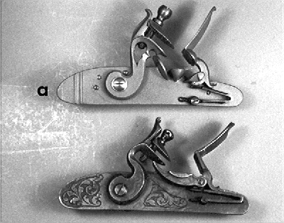
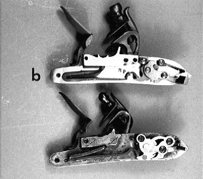
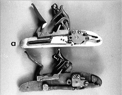
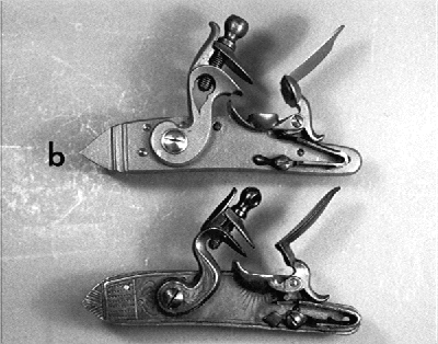
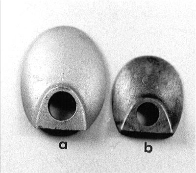
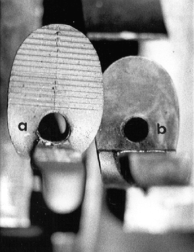
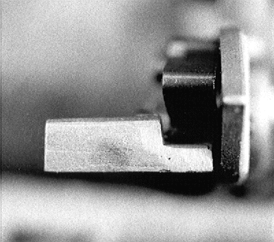
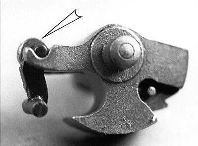
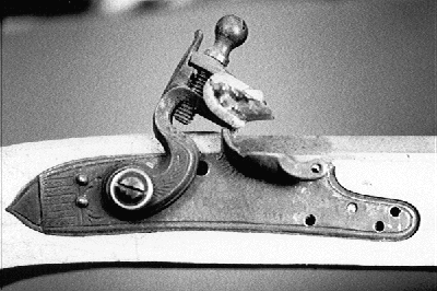
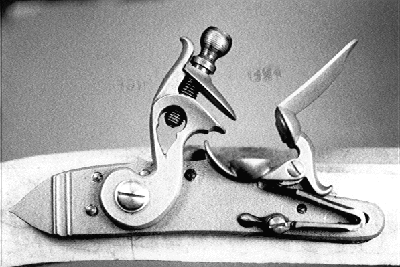
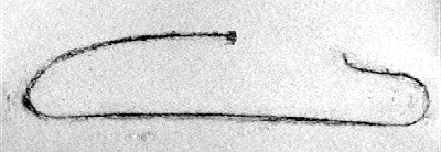
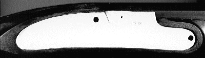
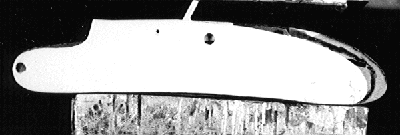
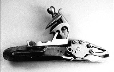
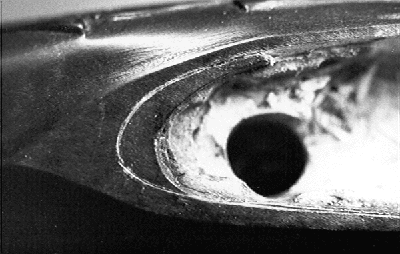
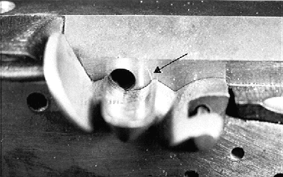
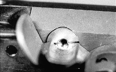
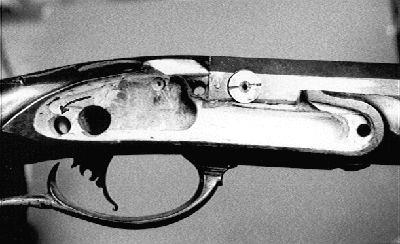
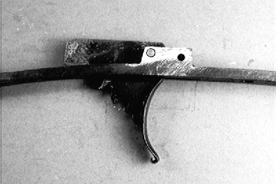
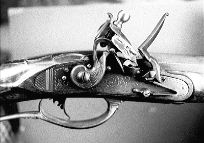
In centuries past, the muzzleloading rifle was an everyday tool subjected to heavy use and frequent abuse. Barrels were "freshed out" (their rifling sharpened by taking out a few thousandths off lands and grooves) again and again as their soft metal "shot slick" and lost their tack-driving accuracy. Stocks were repaired (often crudely by means of iron reinforcement plates or rawhide wrappings) with iron or brass plates when their slender wrists shattered under the impact of a blow or fall. Lock parts failed under repeated impact (I remember with some chagrin when I overhardened a frizzen for a friend, and later, it shattered in front of an audience during a demonstration.) Sometimes the option of complete lock replacement was chosen, either from the standpoint of necessity or merely preference. Perhaps the most well-documented lock replacement on a Pennsylvania/Kentucky rifle was performed in 1800 by the famous gunsmith Durs Egg, on "a fine long Gun call'd a smooth rifle" originally built by John Christian Oerter.1 Lock replacement could be a major production in the olden days. Rigid standardization of parts had yet to become commonplace, and some of the old handmade locks were truly one of a kind. Replacement locks sometimes had plates too small for the existing mortise, or they were of a style inconsistent with the character of the original rifle. Therefore, some fine old rifles have survived to bear mute testimony to the difficulty of finding replacement locks that were stylistically and dimensionally appropriate. There are many rifles out there that could benefit from a lock replacement. Most of the marginal (usually foreign-made) locks available when I started building rifles in the 1950's would not even rate my second thought today. I remember naively buying a dozen Italian-made flintlocks that were so bad that I had to spend many hours getting just two to cycle and spark well. After that educational experience, I sold the remainder to a fellow at a flea market who was making cheap wall-hangers. Some of us have rifles or pistols built or bought years ago that reflect a similar lack of discrimination and taste; yet we would still enjoy using them if only the locks were more reliable or at least reparable. At the time of this writing, L & R Locks has been the only major lock manufacturer that has responded to the need for specific replacement locks (see ad in current issue.) L & R has been providing an expanding range of high-quality American-made locks for newly built custom rifles and fowlers. Now its line of RPL replacement locks will surely be showing up on many rejuvenated TC, CVA, Lyman, Hawes, and Traditions models as well. I had inletted locks during the building of more than fifty rifles, repaired and completed the lock inlets started and maimed by others, and even fashioned custom (read that as "cover-up") plates when all else failed. However, the prospect of retrofitting replacement locks was new to me. But I thought, hey, now that surgeons are transplanting kidneys, hearts, and lungs, why should I not at least attempt a "lock transplant operation?" When the RPL line of locks became available, my sense of curiosity about lock replacement centered around two questions. How simple would it be to replace a lock for which the RPL series had been specifically designed? How much difficulty would be entailed in using an RPL lock to replace a lock for which it had not been designed? Bill Cox, President of L & R Lock Co., knows that my curiosity about muzzleloading matters is marbled with a masochism that leads me into the proverbial "project of no return." Therefore, he was very conservative about my desire to tread the replacement trail beyond the range of locks for which the RPL line had originally been designed. But he probably considers it his civic duty to keep me occupied and off the streets with some project, for within a couple of weeks, two RPL locks showed up together with locks they were designed to replace (comparisons in Fig. 1 and 2). While the two RPL locks had approximately the same plate dimensions as the locks they were to replace, they were different in many functional respects. The RPL's had strong mainsprings and crisp frizzen actions that consistently produced a good shower of sparks. Conversely, one of the foreign-made locks had a mainspring so weak that it would not even cycle because the flint hung on the frizzed face. Another of its problems was the inadequate top-jaw dimensions, compared to those of the RPL shown in figure 3. An associated problem in the design of the foreign-made lock was the lack of any gripping ridges on the interior surfaces of either of the cock jaws (Fig. 4). Even with the flint expoxied into its leather sandwich (which has long been SOP on my flintlocks), it could not be clamped adequately between the tiny smooth surfaces to generate good sparks. Nice internal features on the RPL locks include a widened sear arm (Fig. 5) that provides a lot of room for modification to accommodate a wide range of trigger heights. While this feature would seem to the inexperienced eye to be a relatively minor one, it would be welcomed by anyone (myself included) who has wrestled with heating and bending the sear arm up or down to get the right relationship between lock and trigger(s). As a matter of fact, this would be an excellent feature to incorporate into any lock, whether destined as a replacement or original equipment. Also, for those of us whose middle name is "Butterfingers" the stirrup capture loop in the tumbler arm (Fig. 6) will keep the agile little part from flipping out of its cup and falling into the debris that will camouflage it on the shop floor. In determining the ease with which an RPL could replace one of the locks for which it had been designed, I used an unfinished pistol already inletted with a Russ Hamm lock (Fig. 7) made in the 1960's. The assembly had hung in the rafters for nearly three decades, orphaned by a fellow who commissioned me to build a pistol, provided the parts, then moved away to an unknown address before its completion. When the appropriate RPL was mated with the orphan pistol, it could literally be pressed into the existing mortise (Fig. 8) with only slivers of wood needing removal for a nice fit around the lock plate. Replacement would obviously be so simple that it would be essentially a "no-brainer," which hardly merited description as part of a published article. Therefore, the first of the two questions posed earlier was easily answered. Answering the second question would prove to be much more of a challenge. The patient scheduled for transplant surgery in this case was a fine flint longrifle about twenty years old. It had competed successfully in past local shoots, thanks largely to the accuracy of its heavy Douglas Premium barrel. However, its modified Dixie 1F lock, with its badly worn frizzen and chipped tumbler, did not do justice to the rest of the rifle, and it was therefore a prime candidate for replacement. To make the initial evaluation of replacement compatibility, the old lock was removed and a pencil rubbing was made of the mortise outline (Fig. 9a). The outline was then cut out and laid over the RPL plate to evaluate the compatibility between the two (Fig. 9b & Fig. 9c). This comparison revealed a minor problem insofar as the radius of the nose of the RPL lock plate was a little smaller than that of the 1F plate. To make the RPL fill out the mortise in that area, the nose of the plate was brought to a red heat with a propane torch and spread just a tiny bit with a flat-faced hammer. The generous overhang of the RPL plate at the other areas of the mortise allowed some shaping and slimming to make it more symmetrical with the lock panel. However, care was taken to ensure that the plate was not reduced to the point where either moving parts protruded beyond its edge or where it would not fill the existing mortise. So the moving parts were mounted and their extreme range of motion outlined on the plate with a felt tip marker so as to define the limits of reshaping they would impose. The only internal part that was modified to accommodate plate reshaping was the bridle plate (Fig. 10) in which one of its three screws was converted to a stationary pin. Then the dimensions of the recipient mortise were marked on the plate in several areas as the final limits to which the plate dimensions could be reduced (also shown in 9b). After the RPL plate was ground and filed to its final shape, its nose was kept pressed into the forward portion of the mortise while the rest of the plate outline was scribed into the finish on the lock panel (Fig. 11). Inletting then proceeded rearward by removing slivers from the mortise wall with a pocketknife while taking care not to mar the original stock finish. The atypical dimensions of the original 1F lock caused a problem in the alignment of the RPL pan with the touch hole. While most full-sized flintlocks measure in the range of 0.400"-0.500" from the back sides of the pan fence to the center of the pan, the 1F lock measured only 0.340". So the placement of the original touch hole liner was behind the optimal location for the pan of the RPL lock (Fig. 12). Fortunately, the original touch hole liner was relatively small and threaded 1/4-28. The liner was removed, a 1/4-28 tap was turned into the hole, and its stem used as a pilot to align the drill chuck. After alignment of the chuck over the existing hole, the barrel was moved 0.070" rearward, shifting forward the center of the new hole. The new hole was then plunge milled with a 3/8" end mill (trying to use a conventional drill bit for this operation would result in a ragged job because the bit would lead into the existing hole.) The hole was enlarged to 0.388" and threaded 7/16-20 for a new stainless insert using the installation sequence previously described.4 The hole in this insert was coned from both inside and outside, and was now relocated well within the bowl of the pan (Fig. 13). Once the RPL plate was fully inletted, the internals were inletted one at a time as usual. The RPL sear stretched much farther to the rear than with the 1F lock, so a new hole was drilled to accommodate the sear arm (Fig. 14a). Accordingly, the trigger was moved rearward to bear on the new sear arm location; had the trigger been pinned through the wood of the lock mortise, this would have been a hard situation to repair, since the wood that should support one side of the trigger pivot pin would have been cut away from the existing sear arm hole. As it turned out, it was a relatively easy move because the trigger was pinned in a long boss integral with the trigger plate (Fig. 14b). This modification was an actual improvement, since its somewhat overly long trigger pull was reduced from 14 1/16" to 14 1/8", and moving the trigger back in the guard allowed more access for a gloved finger during winter hunts. So the transplant operation was a success, and after a little engraving and browning, the patient recovered nicely, both functionally and cosmetically (Fig. 15). Care had been taken not to scratch the original finish, and so a touch-up around the lock mortise was not necessary. Note however, that the slight relief at the tail of the lock plate sits a bit below the level of the wood around the lock mortise. If the rest of the lock plate were beveled slightly, the wood around the mortise could be uniformly lowered to bring the tail relief flush with its surroundings. In summary, L & R has taken the guesswork out of lock replacement if one stays within the range of locks for which the RPLs were developed. This range is clearly defined by the instruction booklet that accompanies each RPL lock. Armed with the booklet, a sharp penknife, and the mechanical ability of an orangutan, anyone should be able to do a credible job of lock replacement. Of course, once you step outside the range of replaceable locks as designated by L & R, you are on your own. However, the generous dimensions of the RPL plates would seem to provide ample flexibility (for those of us with a sense of adventure and an urge for improvement in ignition) to widen the range of RPL application. The following considerations should be addressed in determining whether it is feasible (or even desirable) to replace a lock:
In the final analysis, few pastimes are as satisfying as restoring a tried and true mechanical old friend (be it automobile, muzzleloader, or motorcycle) to its former glory. Restoring its function puts a little snap in our spirit as well, if only via the memories of pleasures past. And after all, isn't that the part that lasts? References 1. Shumway, G. 1980. Rifles of Colonial America. Vol. I. George Shumway Publisher, York, PA. 2. Stutzenberger, F. 1998. "Custom locks from commercial parts." Part I. Muzzle Blasts, vol. 59(6), p. 69. 3. Ibid. Part II. Muzzle Blasts, vol. 59(7), p. 73. 4. -----. "Drums and vents." Muzzle Blasts, vol. 59(11), p. 77. |
||
|
|||
|
|||
|
|||
|
|||
|
|||
| |||
|
|||
|
|||
|
|||
|
|||
|
|||
|
|||
|
|||
|
|||
| |||
| |||
|